Thermography and Radiometric Properties
Field of View and Temperature Measurement

Thermographic principles for radiometric temperature determination
This chapter is intended to provide a brief overview of the radiometric temperature measurement with infrared cameras. Prerequisite for a temperature measurement with the IRSX is that the camera has a calibration. This can be recognized by the GenICam Nodes Radiometric Control in the camera properties.
The camera series IRSX is exclusively equipped with thermal sensors. An essential feature of these sensors is the direct proportional relationship to the radiant energy incident from an object on the detector. The radiant energy depends nonlinearly on the object temperature and is influenced by environmental conditions as well as by object parameters.
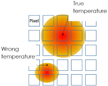
In order to be able to measure the temperature of an object via its infrared radiation, it is essential to know some parameters of the measurement situation. The most important parameters are illustrated in the sketch below.
Emissivity


Determination of the Object Emissivity
Measurement of the Object Temperature with a Thermocouple
Using a Reference Material
Temperature Calculation from camera signal (Flux Linear)

Most IRSX models can store two calibration sets. This allows a replacement of the lens without recalibration. The calibration sets belonging to the lenses can be selected in the GenICam Nodes under the camera property Lens Selector in the group Lens Control. When delivered without a replacement lens, the relevant calibration set is stored under Lens1 as standard. For each calibration set, you can switch between the high and low temperature measurement range using the Temperature Range Selector property.
In the temperature calculation, the external environmental influences such as ambient temperature, must be taken into account. The object temperature can be calculated according to the following formula:

In order to calculate a temperature value from the camera signal, the R, B, F, O parameters are be required. These can be read out of the camera. In addition, the environmental parameters must be known.
Table : Parameters
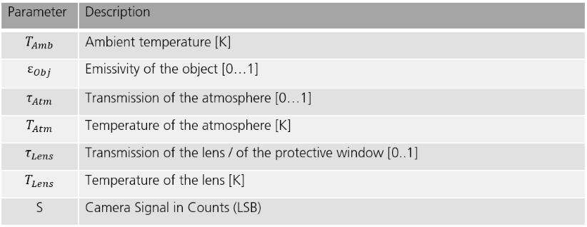
For the transmission of the atmosphere, 𝜏Atm = 1 can be assumed for short distances. If no protective window is installed, 𝜏Lens = 1 can be used. To calculate the temperature from the signal value, the following parameters must first be calculated.
Calculation of the emissivities:


Temperature Calculation with Camera Temperature Linearization (TLinear)
The IRSX series allows to calculate the output signal directly proportional to the object temperature. There are two levels of accuracy, which differ in their dynamics. The function can be selected in the GenICam Nodes under Radiometric Pixel Format in the group Radiometric Control.
The Figure below shows the selection of temperature linearization with the factor 0.04:

Assuming the signal value in a pixel is 7600, the temperature is calculated as follows:
Temperature in Kelvin

Temperature in Celsius

Emissivity Table
Material | Surface | Temperature [°C] | Emissivity |
|---|---|---|---|
Aluminum | polished | 20 | 0.04 |
oxidized, strongly | 20 | 0.83-0.94 | |
Copper | polished | 100 | 0.05 |
oxidized, strongly | 20 | 0.78 | |
Iron | cast, oxidized | 100 | 0.64 |
sheet, heavy rusted | 20 | 0.69-0.96 | |
Nickel | polished | 20 | 0.05 |
Stainless steel (18-8) | polished | 20 | 0.16 |
oxidized | 60 | 0.85 | |
Steel | polished | 100 | 0.07 |
oxidized | 200 | 0.79 | |
Brick | red | 20 | 0.93 |
Carbon | 20 | 0.93 | |
Concrete | dry | 35 | 0.95 |
Glass | 35 | 0.97 | |
Oil, lubricating | 17 | 0.87 | |
0,03mm film | 20 | 0.27 | |
0,13mm film | 20 | 0.72 | |
Thick coating | 20 | 0.82 | |
Oil paint | Mix from 16 colors | 20 | 0.94 |
Paper | white | 20 | 0.07-0.90 |
Plaster | 20 | 0.86-0.90 | |
Rubber | black | 20 | 0.95 |
Human skin | 32 | 0.98 | |
Soil | dry | 20 | 0.92 |
saturated with water | 20 | 0.95 | |
Water | distilled | 20 | 0.96 |
frost crystals | -10 | 0.98 | |
snow | -10 | 0.85 |
Non-destructive Testing (NDT)
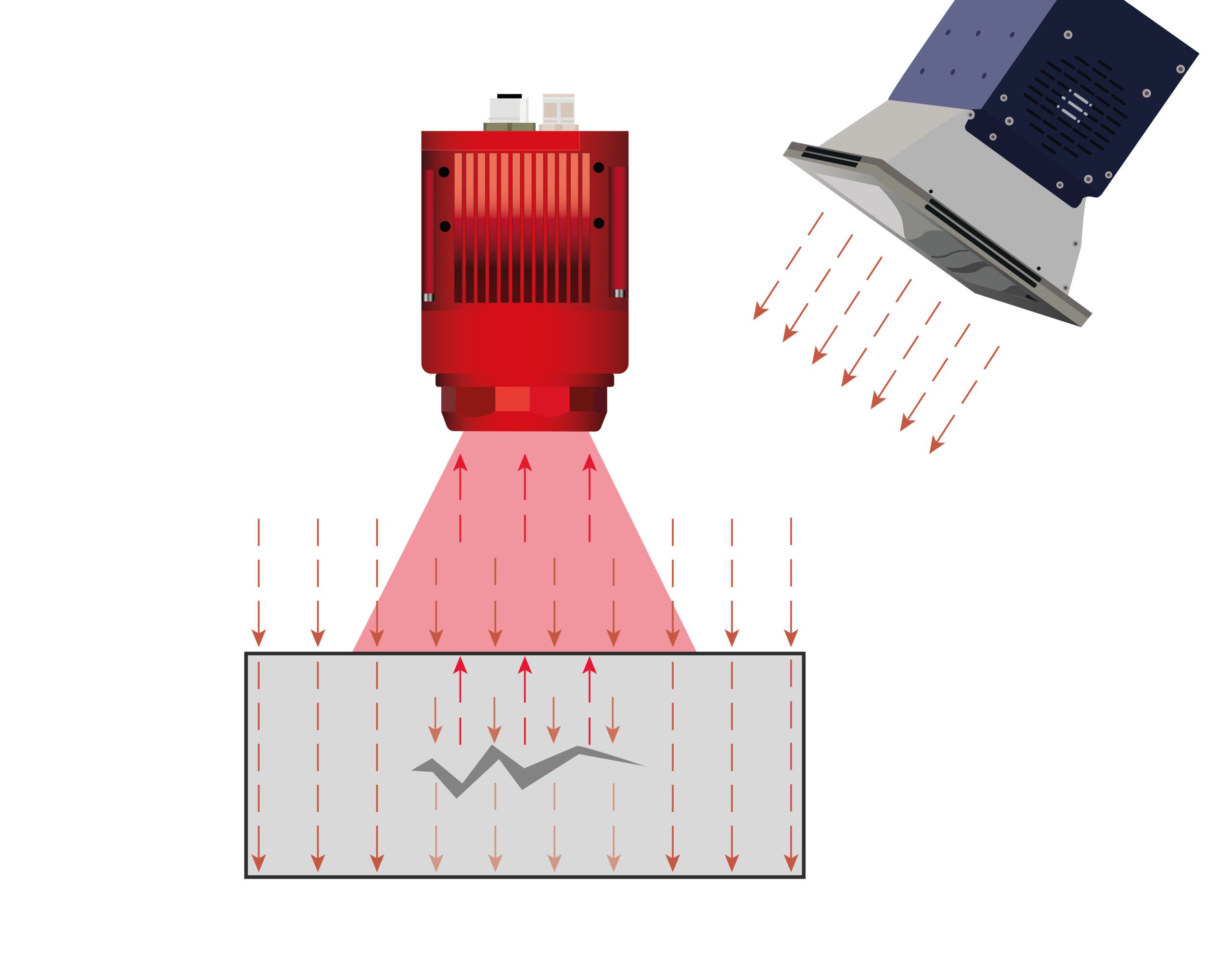
Active thermography, as a method of non-destructive testing, makes it possible to quickly and reliably detect hidden defects such as cracks or delaminations. For this purpose, the component is stimulated and heated by an external energy source. An infrared camera then records the temperature distribution on the surface, which is influenced by irregularities within the material. This results in high-contrast images that enable precise quality control – contact-free, efficient, and without causing any damage to the component.
